Papier Logik sensors are most often used with a development board such as an Arduino.
This powerful and low-cost electronics enables to easily connect your sensors and read related signal on a computer using simple components, serial USB communication (r other wireless systems and protocols) and open source programming and data display environments.
We have collected here basic information to connect and get relevant signals data feedback for each type of the sensors we can produce.
Startup Arduino Program
Arduino boards can quickly be programmed to acquire sensors signals and send data to a computer or another peripheral.
Arduino programs uses dedicated libraries based on C++. Most programs make use of at least a setup function that is launched at startup and a loop function that... loops as long as the board is powered.
Minimalist program to manage a sensor signal
So a minimalist program to declare a signal variable, read and store its value in real-time and display signal through serial will work on any Arduino or other board using the Arduino language and would look like this:
#define BAUDRATE 9600

int SensorValue;

void setup() {
  // initialize serial communication at 9600 bits per second:
  Serial.begin(BAUDRATE);
}

// the loop routine runs over and over again forever:
void loop() {
  SensorValue= analogRead(A0);    // read the input on analog pin 0:
  Serial.println(SensorValue);    // print out the value you read:
  delay(1);        // delay in between reads for stability
}
After optionally defining useful global constant and variables, the setup() function enables to setup the Serial communication. The Serial Library is directly available to enable to send data over Serial Communication protocols and ports. The Baudrate setup a size of bits that are (can be) sent per second. 9600 bps is enough for now.
Next. the loop() function is continuously running and it is used here to read and store the sensor value and then to send this value through Serial so that it ca be displayed.
Note: the last line is a delay() function that is good to set low but at least 1ms for better program stability and efficiency.
Voltage divider
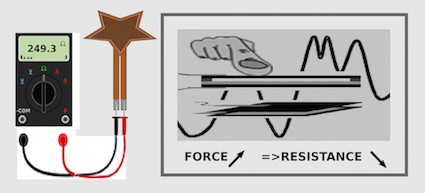
The value read using the AnalogRead() function is a 10Bits Value corresponding to the real-time Voltage of the Read Pin (A0). While Papier Logik are variable resistors whose resistance varies significantly for touch sensors design, the sensor must be connected in combination with a fixed resistor between the Vin and Ground Pins so as to divides the voltage at the Analog Pin read.
The circuit and formula below describes how to connect a resistive force sensor so as to read an increasing value with the load applied.
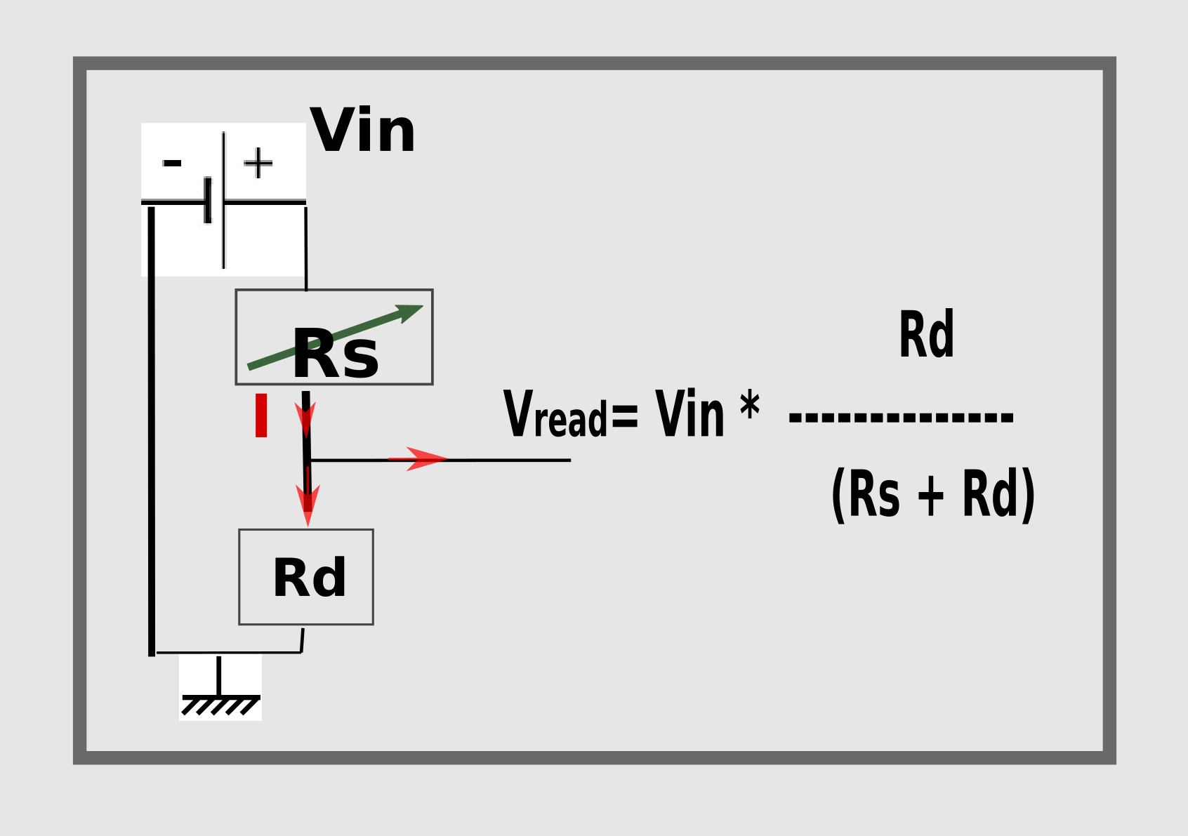
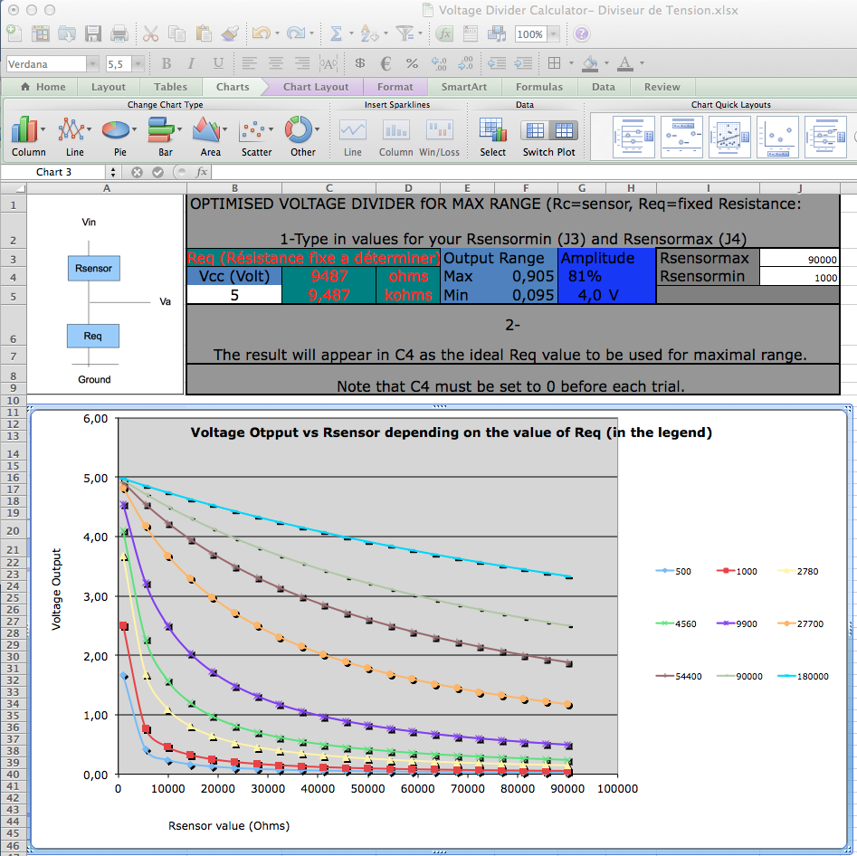
The value of Rd depends on your sensor resistance range. Any Rd value in between this range will enable to output s signal, but the lineairty and resolution of this signal depnds on the choice of Rd. The illustration below provides a link to an excel sheet that enables to cLCULte an optimal Rd value.
Sensor Type VS Connection to Boards
Connecting Force or Flexion sensors
Connecting Wipers (position sensors)
Connecting Dual Force-position
Connecting Multiplexed Arrays
Sensor Type VS Signal Aquisition, type and display
Display Modes: serial Monitor vs Serial Graph
Physical Calibration
PLK-Arduino Library
PLK-Processing GUI