Build Efficient and Sustainable Force Sensors and Learn how to produce sensitive touch surfaces turning real-time load variations from a few grams to more than 100 kg depending on the sensitive area size into variable resistors.
This tutorial was built up as an application example for Papier Logik Development Kits: combining volume conductive papers 1k and 100k, you will obtain variable resistors ranging from of a few kOhms to above the MegaOhm enabling sufficient sensitivity for a plethora of Applications.
Follow these Steps build your first eco-friendly resistor and learn how to customize these concepts.
1- Design the Force Sensing Resistor
1.1- Design the Force Sensing Area
PLK Fabrication Kits provide insulation kraft paper adhesives to be used to build your sensor skin.
This layer should be slightly larger than your expected sensitive surface, as it will be folded on the side to also serve as spacer and laminator.
=> Draw you design onto the design cardboard and add (or include) a few mm borders area as shown below.
1.2- Design the Metal Circuit and connectors location
Small and simple designs such as round or square areas can be very quickly designed here: the goal is to o connect both paper electrodes using wires and/or metal tape and build a connection tail for this 2 poles component.
Larger and more complex designs such as large sensing tiles, long sensors or else sensors with complex shapes can profit finer circuits designs so as to provide more uniform responses along the surface.
=> Draw the location of your connectors or connecting tail aside from the sensitive surface.
2- Build up Electrodes and Barrier Sheets

2.1- Cut Resistive Barrier layer
PLK fabrication Kits provide high volume resistive sheets of the order of 100 kΩ/Sq. These sheets or equivalent materials can be used here as a piezoresistive barrier.
It must be placed between electrodes sheets so as to prevent direct contact between the electrodes. It provides uniform response over the surface when used with electrodes sheet. For sensors of the size of the thumb or below, this layer can be replaced by an insulating spacer made of simple cardboard.
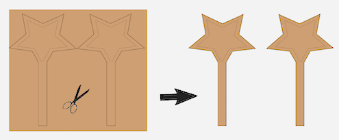
=> Use your design to cut a piece of resistive sheet of the size of the sensitive area.
2.2- Cut the Electrodes Layers

PLK fabrication Kits provide low volume resistive sheets of the order of 1kΩ/Sq to be used here as Electrodes layers when used with a high resistive barrier.
It must sandwich the resistive barrier so as to prevent direct contact between each other.
=> Use your design to cut 2 pieces of Electrode sheets of the size of the sensitive area.
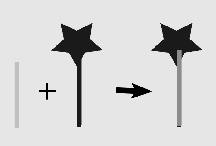
2.3- Mount the metal circuits over the Electrodes Layers
PLK fabrication Kits provide tin-plated copper tape with conductive adhesive to generate connectors onto the electrodes sheet and generate thin internal circuits towards thee components connectors.
The larger or complex the sensor the more refined metal connector will be required over the Electrodes.
The tape has a width of 0.6 mm which is great for the pads locations. It can easily be narrowed into 2 or three bands of a few mm especially for small sensors.
Select the most appropriate circuit design from the examples provided here and draw this design onto your cardboard model linking each electrodes papers to a connection pad.
For each electrode to build Stick firmly the metal tape over the tail and area you defined over your sensitive surface.
3- Mount Electrodes and connectors
3.1- First electrode with resistor layer
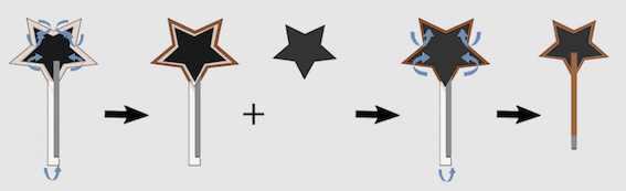
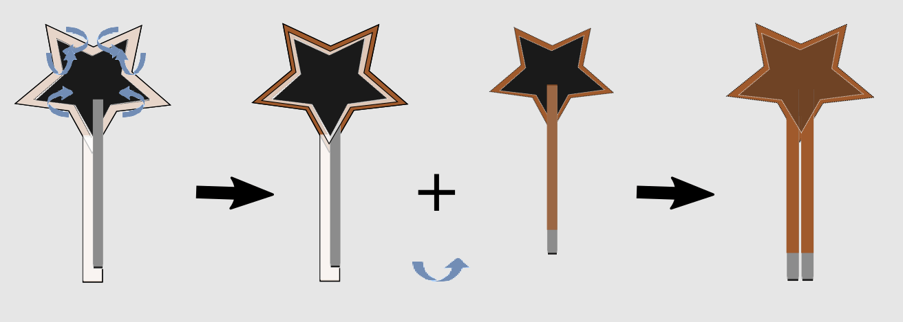
Mount the First Electrode + the Resistive Layer on Top of you sensor using one of the kraft paper support, and the corresponding paper electrodes you just produced:
Tape or glue the electrode over the white layer of the adhesive, and fold the sides overf the edges of you electrodes so as to generate an internal spacer between the 2 electrodes.
3.2- Second electrode over the first electrode and the resistor layer
Mount the Second Electrode in the center of the seond paper and kraft adesive without any resistive layer this time, and without folding the edges immediately.
You can then asseble it with the first Electrode and then fold the kraft paper adhesive to bond the whole.
3.3- More to know:
An insulating support and cover is not compulsory but can be useful for many reasons:
- to enhance the sensor's rigidity and solidity to shear and small impacts.
- to stabilise the default resistance value.
- to adapt the influence of the surface contact and the load input sensity (vs cover rigidity ).
- to provide a support extension for the connectors.
Small sensors of a few inches square such as the ones produced here may simply require a thin spacer made with a classic writing paper and a cutter. The bigger the sensor, the thicker should be the spacer with more refined designs.
Last, connectors can be made using the metal tape with conductive adhesive. The tape provided in the Kits is 0.6cm width and can easilly be cut into bands of 0.2 to 0.3 cm width especially for small sensors.
4- Pre-Assemble & Test
4.1- Test with a Multimeter
You sensor shouLd now be useable but it is still quite fragile. However, it is better to test it and make sure it is functional prior to finish it.
=> Connect you sensor to an ohmmeter and make sure you can read you signal ranging above 100kOhms when no load is applied and goes down to a few ohms when pressing the sensitive surface. Check the troubleshooting pages if you have an issue.
If you do not have a multimeter you can try you sensor using power cells and a leds requiring low power to work, such as the ones found in Fabrication Kits or in electronic devices for visual beedback.
You will however manage to use the appropriate power and work in dark environments to observe lights variations. Check out this page to understand how to master the power of Light!.
If the sensors reacts as expected, you can finalise it by reinforcing it and you can also integrate a paper resistor and a third pin to integrate the voltage divider in your sensor.
4.2- Voltage Divider Design & Test with the computer
Arduino boards and equivalent solutions are widely available to use your sensors with your computer or your phone. However, this takes a very small and simple electronic circuit and an understanding on how to connect a resistive sensor to the input/output pins of a development board.
You can easily build your own voltage divider and a third connecting pad along the two curerent pins using the same materials we used for the sensor. Check this tutorial for more informations.
You will then use 2 or three connectors or wires to plug your sensor to you development board as detailled in this implementation pages, depending on the number of sensors and the board you have.
5- Setup connectors and Reinforce under Test
5.1- Reinforcement Strategies
Depending on how and where you will use you sensor, you must protect more or less its paper layers from shear, friction and moisture. If the sensor is already to be enclosed inside another element that will protect it from all of this, you may skip this step.
If you plan to use the sensor without any protection, you should cover it with the thermoplastic adhesive provided in the kit using the same strategy you used for the paper kraft adhesive.
5.2- Durable Connectors
Connectors are usually the most fragile part of the sensor and should carefully be reinforced and not submitted to any mechanical stress. Most durable connections are done with efficient soldering strategies, but mechanical connectors can also provide long-lasting solution in safe and clean environnements.
thermoplastic glues can also be used as a final touch to insulate connectors from air and prevent oxydations and short-cuts or noises in the signal.
6- Electronic Applications
6.1- Electronic circuits design
Paper FSRs can be used as control buttons and other DIY circuits components can be produced for adapted low power electronic circuits and educative applications of official scholar programs and current technologies applications, as overviewed through the few examples below:
- EduKits: Applied sciences for DIY Technologies
- Paper-Based Electronics: Reinvented Sustainable Technologies
- Paper-Based Electronics: DIY House-Automation Systems Hacking
6.2- DIY Tool for Arduinos and Development Board
Paper FSRs have been used as detection, control or measurement sensors button in any addapted low power electronic circuits as described with the few examples below.
6.3- Embedded systems and Human Computer Interfaces
These concepts have been explore to build hundred of prototypes in the fields of embedded systems such as augmented or connected objects and Human Computer Interfaces such as Video Game controllers, House automation systems or laboratory work benches.
It just takes the appropriate software to turn your sensors signal information into a Digital Music Instrument, a Giga Interrupter, a tactile Carpet or floor embedded system acting as a light control detector, a gaming interface or a Health and Care system, etc...
7- Digital Signal Processing
Building your own electronic device will take you to understand a bit of programming if you want to have a customisable set of tools to reinvent your technologies.
It starts with being able to master the signal coming out of you sensor and adequately use it to monitor event, collect and analyse or measure data, and generate events that can be transmitted to other computers and software to generate sounds, images or any other virtual, electrified or robotised event.
Many open source projects, among which the Arduino softwares, simple basics or else Scratch and App Inventor are great and accessible resources to discover and learn with fun and results the world of programming.
Follow this tutorial if you are ready to optimise the use your sensors with computers and Arduinos.
8- Get Inspired
8.1- Mapping: turn you signal to Events
Once you know how to read sensors signals and you are able to extract useable information from it, such as a signal increase due to a touch event, you can turn this event into anything that a computer will be able to carry on, such as controlling sounds, visual feedbacks or talking to other connected objects and environment such as smart TV homes or Cars!
8.2- Unlimited Applications
Check out the following examples that make you of Paper FSRs for various applications. You may find there each time new Hardware Development Tips & Tricks as well as a few custom softwares based on Max/MSP for each prototype.